Guide To 2024 FSAE Frame Rule Changes
Keep these resources open during your team’s entire frame design process:
2024 FSAE Rulebook
2024 FSAE Structural Equivalency Spreadsheet (SES)
2023 FSAE Tech Inspection sheet
2024 suspension subteam geometry and loads
2024 ergo subteam packaging
2024 drivetrain subteam packaging
The Guide To 2023 Frame Rule Changes has details about even more rules.
The 2024 SES is in process. 2023 SES will be a good start for any teams working before its release. Some changes that are not simply updates for the 2024 rules are also covered here.
There are other rule changes not mentioned here. Just frame and SES topics are covered. And I have skipped over everything that is simply a clarification of existing 2023 policies.
2024 North American SES submission should open one day after 2024 North American registration.
Bring an electronic copy of your SES and electronic copies of any supporting documentation to Tech Inspection. The SES is not and has never been a printable document. I might be tempted to plot a huge copy and hang it on the wall to scribble on during the design process though.
Rule Changes Affecting All Teams
V.1.4.2 Maximum Ground Clearance Under The Lower SIS
In order to continue to align Side Impact, Attenuator, and other safety structure heights, a maximum ride height under their common measurement point will be checked. Please send feedback as to what the ride height window should be under the lowest point of the SES, measured to the bottom surface. Keep in mind that the range of the window will need to be applied to a change the protection structures for 2025. Most likely, this will be a reduction in the maximum height of the IA, but it could also be distributed between lowering the IA and raising all other heights to prevent a worst case scenario.
F.1.11 Primary Structure Envelope
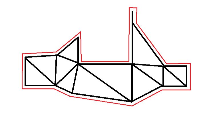
Reminder that while other envelopes expand out through open areas, “Inside The Primary Structure” means literally “Inside Regulated, Triangulated Tubing.”
F.6.5.3 The Shoulder Harness Bar Has ONe Job
That job is to carry the shoulder harness load. We don’t want anything else touching the shoulder harness bar. Get your engine mount loads off the SH and its braces. Accumulator mounts were banned previously. It is reasonable for the SH to support the head restraint, seat, firewall, light bodywork, maybe a brace for a light intake manifold. You are still free to attach components inside the Main Hoop Braces. Keeping components below the SH height is a good policy. For 2024, we are likely to ask for additional bracing for engine mounts that remain on the SH. This rule will be increased from SHOULD NOT to MUST NOT for 2025.
F.8.6 Non Crushable Objects
In the front view of the Anti Intrusion Plate, we really don’t want anything except the Impact Attenuator. Mounts for wing and bodywork should be behind the AIP.
T.1.3.2 Driver’s Legs Inside The Chassis
A reminder that this includes keeping the driver’s legs below the SIS, or in the case of a raised driver, the Primary Structure Envelope as clarified above.
EDIT 15 Oct 2023: We are not concerned with knees above the SIS, we are concerned with hips above the SIS.
T.5.2 Final Drivetrain Shield
Per longstanding policy, the guard around the final drive chain or belt only needs to match the image in the rules. Side guards are not required, because these parts are not moving or creating danger to fingers when the vehicle is stopped.
If there is any hydraulic, pneumatic, or electrical line below the chain or belt, then the guard needs to wrap all the way around the bottom side.
T.9.2.1 LV Batteries INside the chassis
Stricter rule. LV batteries must be inside something we can call the chassis. This does not require regulated sized tubing or triangulation, but the battery must be inside the chassis, not an extended envelope outside the chassis structure, and below the height of the SH.
Rule Changes Affecting IC Teams
T.6.1.7 Pressurized Cylinders INside the chassis
More relaxed limit compared to 2023, will be strictly enforced in Tech Inspection. Pressurized cylinders must be inside something we can call the chassis. This does not require regulated sized tubing or triangulation, but the pressurized cylinder must be inside the chassis, not an extended envelope outside the chassis structure, and below the height of the SH.
Rule Changes Affecting EV Teams
F.10.1.4-5 High Temperature Composites and Adhesives
Specific to composite accumulators or accumulators and mounts with structural bonds only, we will be working with teams to establish testing procedures or a standard knockdown for reduced composites and adhesive properties at the maximum operating temperature of 60°C.
EV.4.3.5-6 Accumulator Pressure Relief
Any accumulator without air cooling holes must not allow high pressure in the container.
Rule Changes Affecting Tube Frame Teams
T.2.4.3, T.2.5.8, T.2.6.3, T.2.7.4 Harness Attachment
The attachment of each part of the harness must go directly to the minimum size tube. There are multiple options, just no more fabricated pieces offsetting a different piece of hardware that actually holds the harness.
In combination with a welded insert or tested monocoque attachment, we encourage eyebolts rated to the 15kN (individual) or 30kN (shared) loads of T.2.4.3 for lap and anti-sub belts.
Lap and anti-sub belts may be bolted or clipped through a chassis tab or tested monocoque insert.
Anti-sub belts have the additional option of wrapping around a Size B tube that runs straight across the car between the Lower SIS tubes. Control for spacing and substantial protection against ground abrasion must be provided.
Shoulder belts may wrap around the SH, bolt through a welded insert, chassis tab, or tested monocoque insert, clip to an eyebolt or tab, or wrap around hardware tested in conjunction with the monocoque attachment.
Tab sizing, as calculated by the SES, will have to show shear equivalence to the loads of T.2.4.3.
Rule Changes Affecting Monocoque Teams
F.4.3.2 Three Point Testing
d. The thickest core used for any given layup must be tested, and scaling will be restricted to 50% of the tested core without triggering a new test.
e. Derived properties may only include panel deflection up to 50mm. That’s a lot of deformation in a structurally critical part of a chassis or accumulator. This is directed at instances where teams want to benefit from the properties of single skins that is only reached when the deflection was 100mm or more.
f. The calculation of absorbed energy must use the integral of force times displacement. We really, really want you to understand energy absorption from deformation, plastic and elastic. However, after a safety issue, this will be automated in the 2024 SES. We also discovered that the 2023 SES was not including plastic deformation in its baseline for monocoque panels (except the SIS.) We do not expect teams to have many problems, just get more realistic numbers as all monocoque sections are scaled to a comparison similar to the SIS energy comparison.
For the SIS itself, we will be enforcing the entry of the MINIMUM floor width and properties between the Front Hoop and Main Hoop for the horizontal contribution to equivalence.
At this time, we will continue to allow multiples of the tested layup to increase equivalence. For local reinforcement, additional untested plies may be used. They need to be shown in the SES, and may not interrupt the tested skin-core-skin layup, including scaling. Extra plies go on the outside of the equivalent sandwich only, and many not be counted towards equivalence without triggering a new test.
F.5.7.7, F.7.1.4, F.7.4.3 Mono Inspection
Aluminum FH must have an inspection hole pre-drilled.
Pick the lowest stress spot in each regulated monocoque section except the SIS and drill a 4mm through hole for a caliper depth inspection.
We will not consider this inspection hole as removing panel height.
Leave a 25mm gap at one end of a laminated in Front Hoop to inspect the hoop itself.
F.7.4.1 BoLTED FRONT HOOP MOUNTS
This has no effect on Front Hoops laminated into the monocoque. The intent is for the mounting requirements for bolted Front Hoops to match the mounting requirements of bolted Main Hoops: minimum thickness, gussets, boxed to the hoop. I’ve sent feedback that I forgot to include a welded aluminum option.
F.7.5.3.b No SIS Vertical Openings
No side view openings between the Front Hoop and Main Hoop in the Side Impact Structure. Exit the wheel motor cables ahead of the Front Hoop and behind the Main Hoop. Same goes for the fuel fill, any cooling, etc.
A hole used by a fastener is not an opening, it is an attachment.
Monocoque attachments are required by rules in this area.
Their size (~8mm OD) is minimal compared to panel heights.
Additional attachments will not be a problem. They are also structural.
Cooling, electrical, hydraulic etc. passages are not structural.
They reduce the monocoque Side Impact performance.
F.7.8.8 Solid Monocoque Attachment Points
F.7.8.8 requires solid inserts enclosed by the inner and outer skins, or local elimination of any gap between the inner and outer skins. This has been narrowed to apply to roll hoop and accumulator mounts whose equivalence is calculated by the SES. The rule does not (and was not previously intended to) apply to suspension mounts, though local core removal with no solid insert must be subtracted as a hole in minimum panel height. And monocoque harness mounts are physically tested. As long as the test piece reliably passes the test, and the design is the same as the car, the design is not restricted, though the same practices will be beneficial.

