Engineering A Lighter Chassis, Part 1
Using geometric properties to design a better tube frame.
MULTIPLE MINDSETS
Different approaches are needed for regulatory requirements and performance optimizations.
The Design Event is a thesis defense.
Design Judges are interested in long, thorough discussions of the performance tradeoffs of mass reduction, suspension location, torsional stiffness, etc.
None of that matters during Structural Equivalency Spreadsheet (SES) Review and Tech Inspection.
SES Review and Tech Inspection will always be a rules and safety checklist.
Safety is the most important. We are not playing around.
We have a hundred other teams to inspect.
Design your chassis to make our inspection easy.
We scrutinize any calculated equivalence that is only slightly above 100%.
Any mistake might drop the equivalency below 100%, and the chassis will not be approved.
We want you to send in a document and build a car that is obviously, easily meeting all rules and equivalences.
After graduating, come back and volunteer.
mailto:collegiatecompetitions@sae.org
Especially if you filled out the Electrical Safety Form (ESF) or Structural Equivalency Spreadsheet (SES).
As of 2023, the limiting factor on the size of the EV competition and the length of the EV waitlist is the number of ESF and Electrical Tech Inspectors.
When you are working professionally, you will always have to deal with regulators.
You will have to check off everything on the list.
You will wish for color coding.
Guide To 2025 Frame Rules Changes
Guide To 2024 Frame Rules Changes
Guide To 2023 Frame Rules Changes
Guide To 2022 Frame Rules Changes
BIGGER, STRONGER
The amount of cross-sectional material is 1::1 proportional to the resulting strength of a part in tension.
Bigger = heavier = stronger.
Make a table of different materials. Include the ultimate tensile strength (UTS), yield strength, modulus of elasticity (E), and density.
Start with the rules 1000-series Mild Steel and rules 6061-T6 Aluminum values.
If you have composites data, you can include that too.
Keep adding materials over time: other steel alloys, other aluminum alloys, other metals, polymers.
You can have a row for pine along the grain, and another row for pine across the grain.
For a given test load, calculate the diameter of the cross section needed to carry the load in tension.
Add columns for compression and shear.
For a given length of that diameter, calculate the mass.
Across different metals, the difference in strength::mass ratio is usually much smaller than the differences in yeld, ultimate tensile strength, or density.
| UTS | Yield | Density | 15kN Yield Cross Section |
15kN Cross Section Mass |
Load/Mass = Yield/Density |
|
|---|---|---|---|---|---|---|
| MPa | MPa | g/cm^3 | mm^2 | g/mm length | kN/(g/mm length) | |
| Mild Steel | 365 | 305 | 8.0 | 49.2 | 0.39 | 38.1 |
| Mild Steel, Welded |
300 | 180 |
8.0 | 83.3 | 0.66 | 22.5 |
| 6061-T6 | 290 | 240 | 2.7 | 62.5 | 0.17 | 88.9 |
| 6061-T6, Welded |
175 | 115 | 2.7 | 130.4 | 0.35 | 42.6 |
In the example above, Aluminum 6061-T6 is 34% the density of a 1000-series steel.
But the mass of an aluminum cross section for a given load is closer to 50% of the mass of a mild steel part.
The relationship is the same for the strength to mass ratio, and of course, there are much stronger steels with the same density as mild.
You might add a column for modulus in the table and multiply by the area moment of inertia (MOI) to get a starting idea about stiffness.
And stiffness to mass ratio.
But design for stiffness is less about material selection, more about putting material in the right places so nothing breaks while being bent.
TO UNDERSTAND ANY CHASSIS
YOU MUST FIRST UNDERSTAND A SINGLE TUBE
To balance one force on the end of one lever, if the second lever is much shorter, the second force will be much higher.
Give me a long enough lever, and I can break anything.

On a seesaw that is balanced, the forces on both ends and the pivot are creating an internal bending moment that is trying to break the seesaw in half at the pivot.
Force_A * Length_a = Force_B * Length_b = Moment_m

The top of the beam is reacting the bending moment in tension, the bottom is reacting the bending in compression.
The further above or below the centroid, the more of the load is reacted.
Stress = Moment_m * height_from_centroid / Area_Moment_of_Inertia
The height of the beam is analogous to the length of the lever balancing the moment.
In a continuous cross section, the area moment of inertia grows exponentially with height.
This decreases stress exponentially, despite stress increasing linearly with height from centroid.

A beam with very little height in bending will experience tension and compression forces many times the input at the end of the lever, and exceed its maximum stress and fail much sooner.

This is why gussets are so effective on brackets.
Material close to the centroid cannot efficiently react bending.
As the moment increases linearly from the end, the gussets get linearly taller, placing a fraction of material further from the centroid to react the linearly increasing moment.

This is why we make lots of static structures out of I-beams.
The top and bottom flanges are spaced apart to efficiently carry all the bending tension and bending compression.
The web carries the shear load.
This is also why we make carbon fiber structures as skins sandwiched around core material.
And exactly the same principle applies to tubes.
The larger the diameter or rectangular side measurement, the higher the area moment of inertia (MOI) is, the stiffer the tube is.
The higher the MOI is, the more bending load the tube can carry.
The top and bottom of the tube are doing almost all the work in bending.
Stress at the maximum distance from the centroid is the limiting factor.
Material in the middle has almost no effect, like a tree with a hollow center..
Tubes maintain high MOI in bending as the I-axis is rotated in directions other than horizontal, and in torsion along the J-axis, where I-beams are relatively weak.

Flip the original lever diagram upside down, and now it is the familiar beam simply supported on both ends, with an non-centered load.
The sign of the moment diagram is reversed, but the absolute value and all the other concepts are the same.
TUBE CANDIDATE SELECTION
For steel tubes, the SES checks:
minimum wall thickness vs. rules
minimum OD/square measurement vs. rules
minimum cross sectional area vs. rules
minimum MOI vs. rules

Make a scatter plot of the tubes you can buy vs. the required area and moment of inertia of the different rules sizes.
Increasing from tube Size C to Size B to Size A can be legally accomplished by increasing wall thickness at the rules minimum 25mm diameter.
But the only way to meet the MOI requirements of Size D is to increase diameter.
Doubling the wall thickness and mass from a 25mm size B tube is nowhere near stiff enough.
The effect of diameter (distance from centroid) is much larger than the effect of wall thickness.
Note the minimum 1.2mm WALL Size D round tube is 101.6% the mass and 214% the stiffness of a minimum DIAMETER size B tube.
A minimum 2mm WALL Size A round tube is 99.4% the mass and 153% the stiffness of a minimum 25mm DIAMETER Size A round tube.
Free stiffness, at least from a mass perspective.
By replacing every tube in the chassis with a 2X stiffer tube, will the whole chassis be 2X stiffer?
No.
Second moment of area math is only valid for closed sections, not spaceframes.
But according to some old simulation sweeps, making every tube 6X stiffer led to 3X higher torsional rigidity for that particular chassis.
Note the 20mm diameter, considered non-structural by rules, barely reaches Size C stiffness even when it is heavier and has much thicker walls than a typical roll hoop tube.
TUBE MATERIAL SELECTION
In FSAE, you may not build a more efficient steel chassis by using less steel in a stronger alloy.
Per rules, all steel is assumed to have 1000-series properties.
Values are provided for ultimate and yield strength in the middle of the tube.
Values are also provided for the reduced properties in the heat affected zone (HAZ) around a weld.
Welded properties are present at all tube intersections, where moments are being reacted.
4130 carbon steel, for example, has higher yield and ultimate strength than 1000-series.
However, in the heat affected zone (HAZ) around a weld, the properties are no better than 1000-series.
When considering node strength, where moments are reacted, there is no strength or safety advantage to using 4130 for chassis construction.
Therefore, the rules minimum wall and diameter requirements do not change when the chassis is built with 4130 tubing.
Higher strength steel alloys can absolutely give higher performance in other parts that are not sized by rules.
Beware of the performance loss in welded steel assemblies that are not fully heat treated after welding.
And any welded repairs or welded modifications will reduce local properties, or require the entire component to be heat treated again.
Factor in the large size, and it is very expensive and impractical to heat-treat a tube chassis.
For tubes other than steel, the monocoque SES checks:
minimum wall thickness vs. rules
minimum OD/square measurement vs. rules
strength * cross sectional area vs. rules steel strength * rules area
modulus * MOI vs. rules steel modulus * rules MOI
Think about the following questions:
Why do steel bicycle frames, aluminum bicycle frames, and carbon bicycle frames look different?
How could a sheet metal steel upright and a billet aluminum upright have approximately the same strength, stiffness, and mass?
Why does a monocoque look different from a tube frame?
Re-read Chris Bachman’s Design of Strong, Stiff, And Light Structures And Joints
THE CHASSIS DESIGNS ITSELF

a.d.Tramontana Front Suspension, via Wikimedia
Leave an easy comfortable margin for all templates.
You will not get a Tech sticker if you fail any template.
cockpit opening
driver leg volume.
a rules 95% male (Percy).
Every team member, because everyone should be able to comfortably drive the car.
The rules give a list of required tube locations and required sizes.
There are bulkheads and roll hoops.
In side view, they must always be connected by an upper tube and a lower tube that are fully triangulated in between.
There are many examples on the tube frame tab of the FSAE SES.
The powertrain needs spaces in the chassis.
Ideally, every tractive battery mount should be at a node.
And last of all, the suspension needs attachment points.
Ideally, every suspension attachment should be at a node.

The required upper, lower, and diagonal tubes approximate a 2-dimensional truss on each side.
In a triangulated 2D truss, there are no openings with more than three sides, and every tube is in pure tension or pure compression (2 force members).
Triangulation also minimizes the force at each welded node.
Pure tension and compression equals no bending moments to react.
This is the lightest, this is the strongest, and this meets the rules.
Non-triangles create bending in the tubes and at the nodes.
Compared to triangles, non-triangles fail in bending orders of magnitude earlier and increase deflection by orders of magnitude.
When you measure the torsional stiffness at a series of points from front to back, the shape of the graph usually looks like the shape of the chassis.
It’s the same concept as tube diameter.
Stiffness is higher where more triangulated tubes are spaced further apart, and lower where fewer triangulated tubes are placed close together.
Like any springs in series, the softest section has the most influence.
I could not possibly make the previous sections better than this video demonstration.
Intro to Racecar Engineering Episode 3: Strength and Stiffness
STRAIGHTEN THE LOAD PATHS
The straightest load path is the lightest, strongest, and stiffest load path.
Loads point in straight lines between reactions.
If material is not centered on the line connecting the reactions, the material is in bending.
A load through two tubes with different angles creates bending loads.
As a component of triangulation, the rules require a bracing tube in side view any time a tube changes direction.
Bending is eliminated if all three tubes are in the same plane as the load path.
The effects are greatly reduced if the bend is in a different plane than the triangulation.
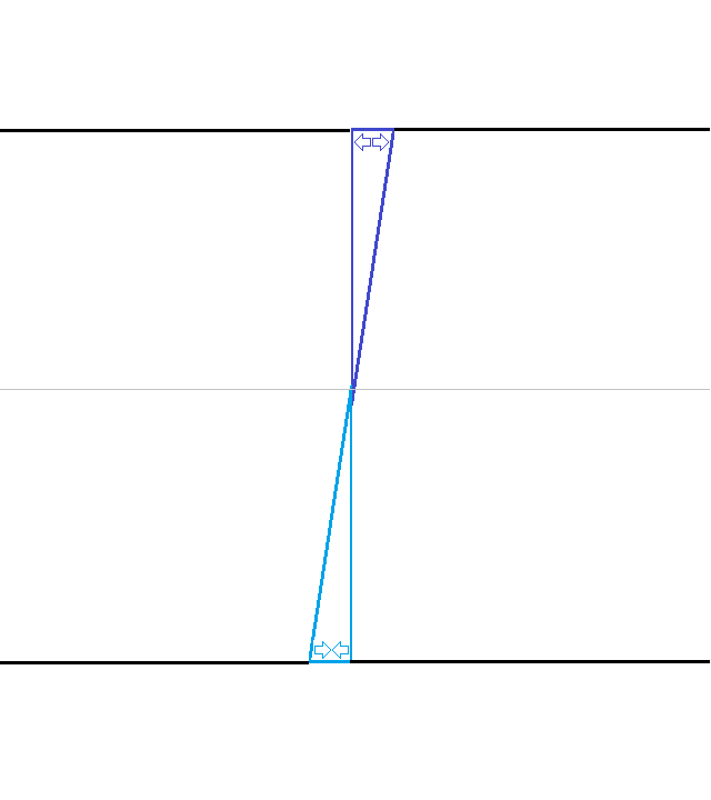
Consider a bent Upper Side Impact member.
The load capacity of the member is reduced by the creation of bending loads.
The driver is in the way of triangulation in the plane of the bend.
Therefore, in addition to a side view tube at the bend, the bent Upper SIS requires a larger diameter Size D tube with 151% the bending capacity of the Size B for a straight Upper SIS.
Using wishbones as an example where you have more design freedom, a triangulated design with every section in pure bending or compression can be very light.

Efficient minimal control arms, via Wikimedia
Much more material is required to carry the bending load when the load path between two points is not straight.

Single outboard left, dual inboard right, via Wikimedia
If memory serves, my team yielded our billet Flying Number 7 shape control arms (even more extreme than the example above) by tapping the brakes the first time we pushed the car out of the shop.
I’m guessing the FEA was only blue for front view tension.
The next generation was consummate V-arms, the next generation was A-arms.
I’m not sure I learned anything until much later.
INCREASING CHASSIS PERFORMANCE AND EFFICIENCY
Use the concepts above to put the smallest number of tubes required by the rules in a starting position.
Move the dots and the tubes around to make triangles to connect the dots.
Add other tubes needed to complete the chassis.
Ideally with the smallest possible number of tubes.
Ideally in the shortest length.
Ideally completely straight load paths, or with very shallow changes in direction.
The rules require, with their 2D truss approach, effectively two parallel ladder frames.
This provides good structures and load paths for front, side, and rear impacts, and reacts the roll hoops in a rollover.
The rules do nothing to optimize torsional stiffness.
The rules are written for 2D triangles in side view, not 3D tetrahedrons that would leave no space for the driver, templates, or powertrain.
Estimate mass and simulate a torsion test for each design iteration.
Try adding or subtracting tubes.
Tubes in the floor and the top of the chassis can have a big influence.
Try different size tubes.
Try square or round tubes.
Compare different materials where that is part of the design space.
Charles Kaneb reminds us that torsion is not the only important load case.
Given enough iteration, the design is likely to converge on an efficient triangulated geometry.
An efficient design will remain sensitive to individual tube sizes, but be less affected by minor changes in tube position or the direction of some diagonals.
The preferred design may not have the highest torsional stiffness::mass ratio.
And may not be the lowest mass, or the highest torsional stiffness.
Make sure to document the calculations that drive chassis selection.
SUSPENSION EFFECTS ON CHASSIS DESIGN

Notice the high bending on the lower control arm, via Wikimedia.
Draw a free body diagram for the upright and calculate the upper and lower control arm loads through travel for cornering, acceleration, braking.
A good starting assumption is the lower control arm load will be loaded at 150% of the lateral, acceleration, and braking tire force.
And the upper control arm will be loaded at 50% of the lateral, acceleration, and braking tire force in the opposite direction of the lower control arm.
Resulting from the height from the tire contact patch to control arm attachment points.
At a glance, the example above is more extreme, closer to 200% lower, 100% upper.
Due to the angle, 150% of vertical load is a reasonable starting estimate for a pushrod into the rocker.
120% for a direct acting spring, since the angle and motion ratio should be less extreme.
Calculate those out through loading and travel.
Torsional stiffness comes from triangulating the front and rear rocker mounts / shock pickups.
Floor triangulation is good for minimizing deflection from the lower control arm.
But there is a driver and a template between the optimal location for upper control arm pickups.
The upper control arms will put the chassis in bending almost no matter what.
The loading is not in the same plane as the 2D truss.
Fortunately, this is the lowest load in a double control arm suspension.
A lot of chassis designers tie themselves in knots trying to get every suspension pickup at a node.
In side view, this at least maximizes the material at the location.
But forcing the chassis to the upper control arms often leads to extreme chassis geometry that is terrible from an impact, torsional rigidity, and manufacturing perspective.
Upper control arm mount bending and deflection are unavoidable, so consider:
moving the pickups forward or backward
when the wishbone axis is parallel to the center plane, there is no kinematic change
only internal and mount forces are affected
straightening front to side impact load paths
moving one or both upper control arm attachments away from nodes.
Engineering for the additional loading and deflection mounting off the node creates:
Determine the amount of deflection with the upper control attachments at a node.
Compare different attachment locations that are not at a node.
Target other locations that are already heavy and stiff, like the front roll hoop.
Then add material in the right places to reduce deflection to an acceptable level.
Upsizing one tube might significantly help deflection and torsional rigidity.
SES and Tech will ignore any tube <25mm diameter or <1.2mm wall.
Distance along the axis for the front or the rear wishbone attachment has no kinematic effect.
It only affects the internal forces in that control arm.
Longitudinal tire forces are reacted by the control arm widths.
At extremes, a truss design might be needed for outboard steering clearance.
This is a place to do brief hand calculations for each concept, then quickly switch to FEA for more granular analysis.
Tension, compression, bending, shear, and even torsion get involved in the interface between the upper control arm and chassis.
SES Reviewers and Tech Inspectors care about chassis load paths and triangulation.
They do not care about your suspension geometry.
Compared to safety and rules, its forces are small, and its kinematics are not important.
SES Reviewers and Tech Inspectors do not care about your FEA.
Professional level audits are not practical and do not scale.
Design Judges care about load paths and triangulation.
Design Judges might care if your upper control arm attachments are not at a node.
Use FEA for design judges when the tubes and the mounts want to be in different places.
Show comparisons for mass, stress, deflection, torsional stiffness, kinematics, laptime, cost, and manufacturing times.
The same technique will show the improvement from a permanent or removable strut brace front and rear.
In my opinion, it is much more important to put the harness attachments near nodes.
I guarantee the loads are higher.
HOW TO DESIGN EFFICIENT EV BATTERY MOUNTS
Open the SES and follow along the guidance images with the next few paragraphs.
Fully enclose each battery module in its own six sided compartment.
Walls and floors are required around each module: front, back, left, right, top, bottom.
The modules inside each compartment provide important additional structure and rigidity.
An imaginary box around just the battery modules makes up the majority of the tractive battery mass.
Attach the mounts directly to the compartments where the modules touch.
Do not allow gaps, other compartments, or ducts to increase the distance between the mounts and the module structure.
A higher offset increases the bending, which increases the size of the mount, which must pass through the other compartment directly back to the module walls.

Locating a mount at each corner of that box will:
React the moments on the left and right of that box mass.
React the moments on the top and bottom of that box mass
React the moments on the front and rear of that box mass.
FSAE corner attachment rules assign a lower test load for following this basic engineering principle.
Also, there are never more than two mounts in a line, so this approach automatically respects the limit of 2 mounts per triangulated tube segment.
Adjust the chassis so there is a triangulated node as close as possible to each mount location.
If possible without stretching the tractive battery mounts out, attach directly through a chassis welded insert or monocoque hard point.
When this makes the tractive battery mounts too large, the fastener should be approximately halfway between the box around the cells and the chassis surface.
Pay attention to easy tractive battery removal and installation.
Use shear pullout, shear tearout, and bending math to size the mounts for the test load.
Even if you do not have a deep background in statics, the SES shows all equations and comparisons being made.
When the tractive battery mounts stick out from the imaginary box around the cells, use gussets to brace against the test load normal to the mount.
If the chassis mounts are not directly through a welded insert into the tube, use gussets along the length of the tube and across its width.
The FSAE SES entry process for the tractive battery mounts attempts to make gusset design procedural, at the cost of only calculating a small number of shapes.

Part 2 will discuss the application of these concepts to monocoque design and rules compliance.