A Guide To FSAE Axles
Unless your FSAE car uses hub-mounted electric motors or a solid rear axle, you need to transmit the energy from your chassis mounted engine or motor to your suspension mounted driven wheels. For the context of this article, we’ll examine the axles of a conventionally arranged FSAE car with a fixed rear differential and an independent rear suspension.
As the driven wheels move with the suspension, their position changes relative to the output of the differential. This requires a connection that allows for change in length and misalignment between the ends. There are many ways to accomplish this; old Formula 1 cars used a rubber coupler between the gearbox output and the end of the axle to allow misalignment and change in length. Other cars use a two-piece halfshaft where the parts are splined together to transmit the torque and allow for length change, while using a universal joint or CV joint at either end.
Most FSAE cars utilize an assembly with two universal joints and a fixed-length shaft, where one or both of the universal joints allows for the change in length.

There are many types of universal joints, but the three most commonly seen on FSAE and SAE Baja cars are the U-Joint, the Rzeppa Joint, and the Tripod Joint. All three joints have some similarities and some differences.
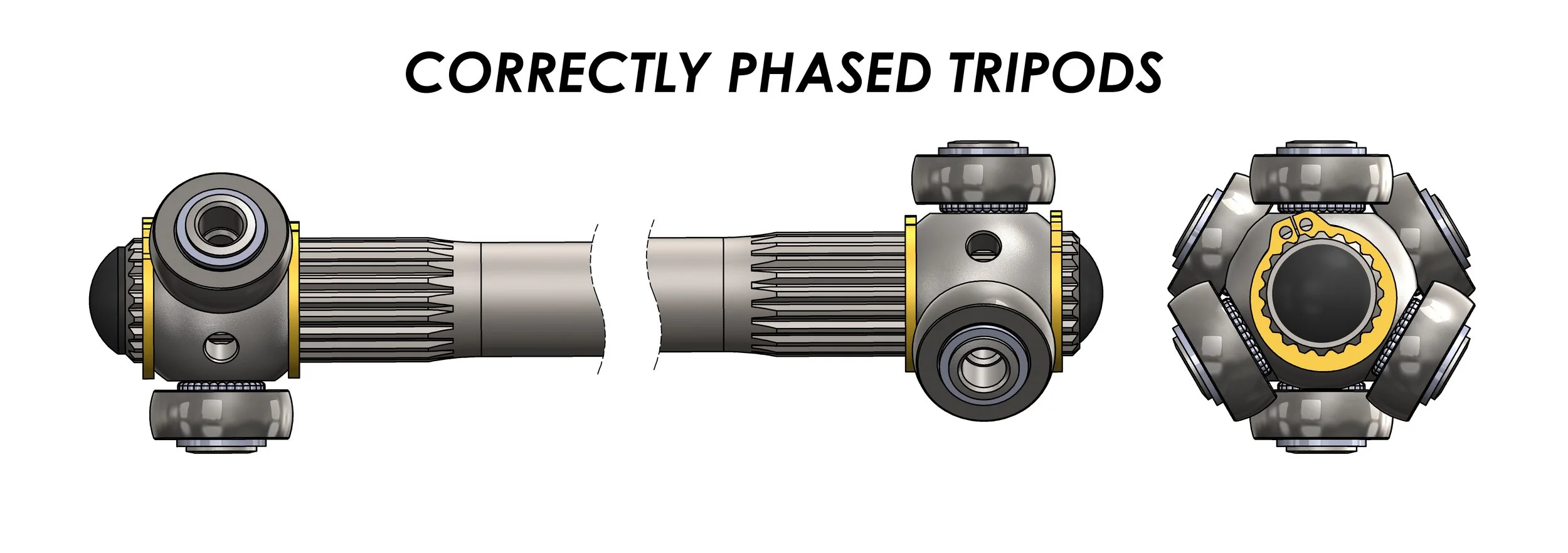
U-joints, unlike Rzeppa and Tripod joints, do not have a constant velocity between input and output as they articulate. This causes the input and output to change phase relative to each other, and can be minimized by using two U-joints, one on each end of the shaft, with the joints phased 90 degrees from each other and the misalignment angle equal at both ends.

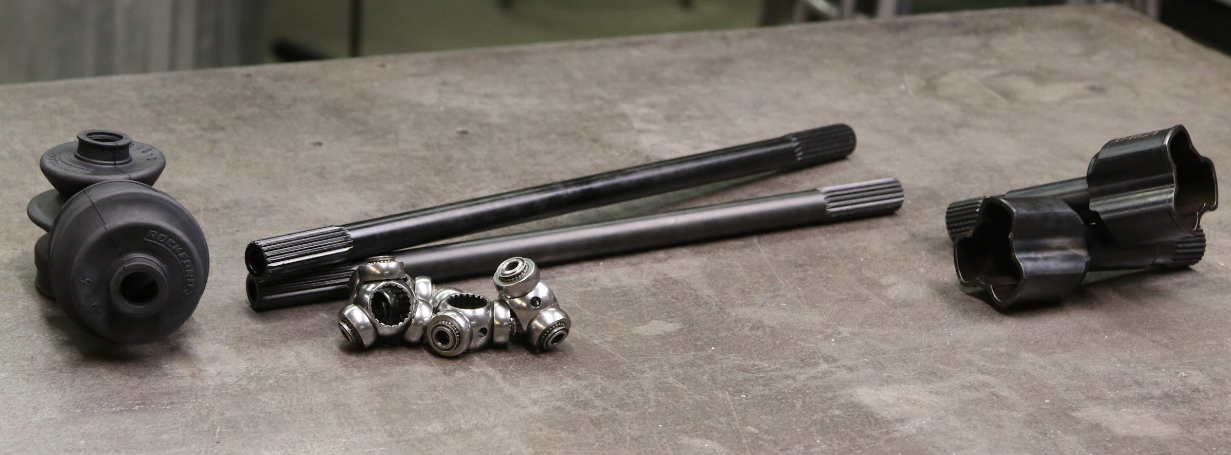
U-Joint, 1-driving fork, 2-bearing shell, 3-needle bearing, 4-sealing, 5-lock ring, 6-cross, 7-joint bolt, 8-driven fork, by Štefan Hajdu, Ladislav Rolník, Juraj Švoš, via ResearchGate.

U-joints correctly phased and angled to cancel Cardan effect, via Wikimedia
Rzeppa and Tripod joints are types of constant velocity joints, which as the name suggests keep the input and output at the same velocity with no change in phase.
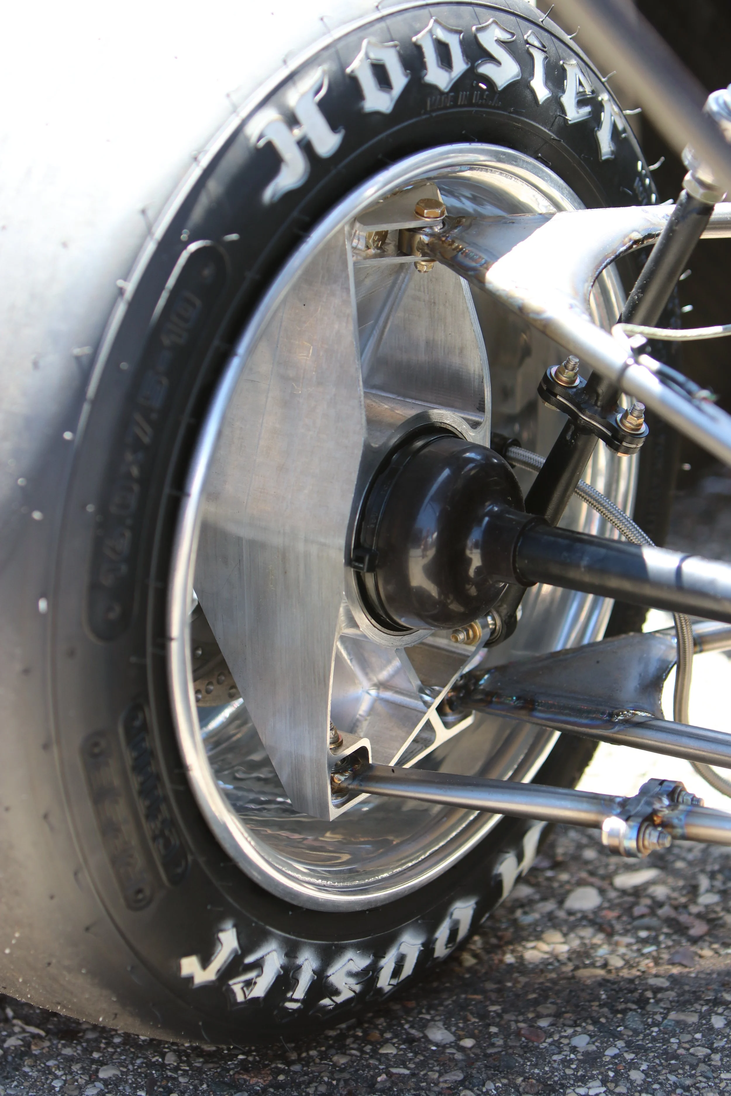
Rzeppa joints allow for high misalignment and are very strong, but in low power applications they can be heavier and larger than an equivalent tripod joint if you’re choosing from the commercially available sizes. Rzeppa joints are available in both fixed and axially-plunging versions, which allow for change in length.

Rzeppa joint, via Wikimedia
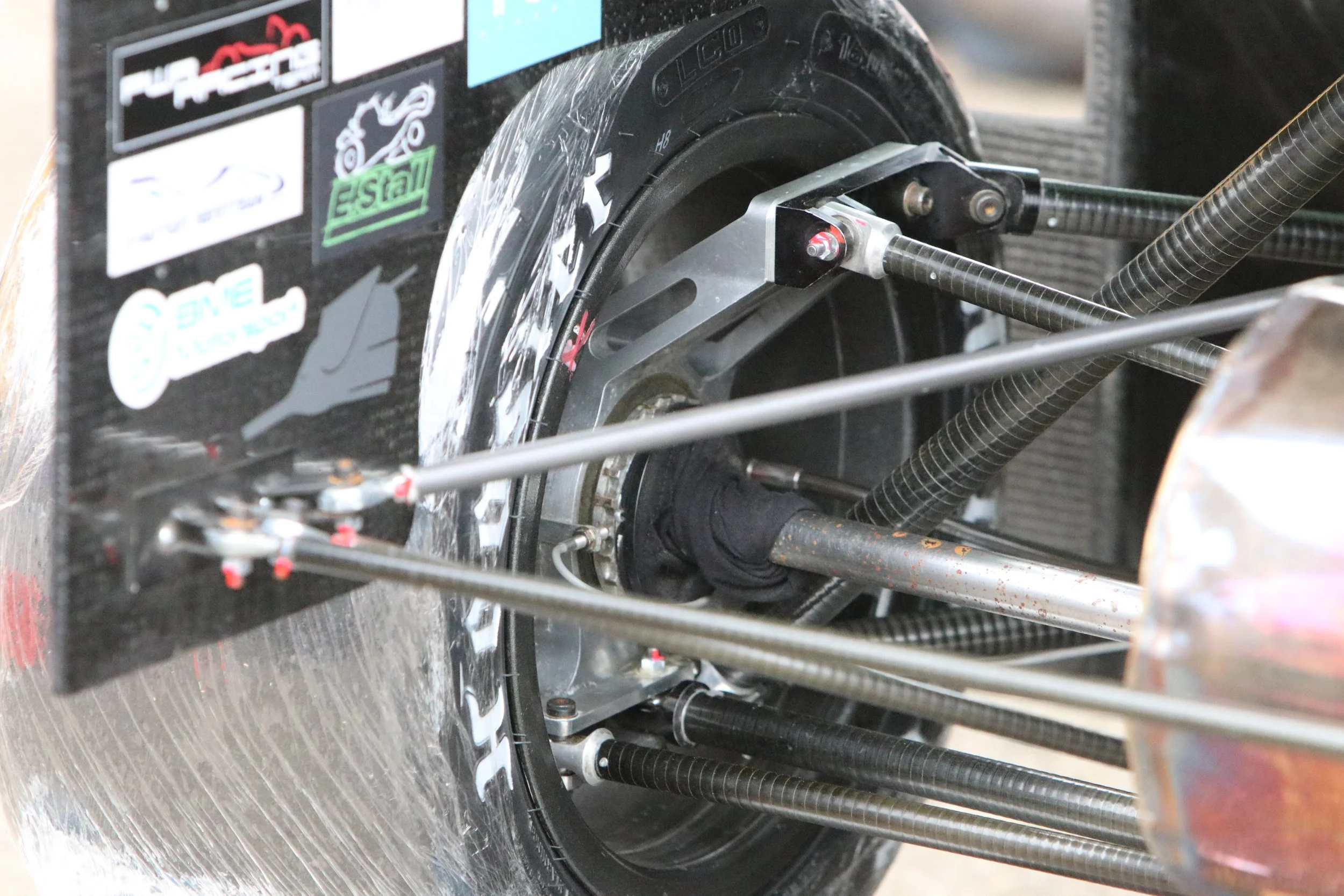
Tripod joints typically do not allow as much angular misalignment as an Rzeppa joint because angular misalignment can cause contact between the halfshaft and the housing of the tripod joint. Due to their smaller size, a tripod joint housing can often be incorporated into the wheel hub which can save significant weight.

When designing the halfshafts for an FSAE or Baja car you must ensure that your design allows for the required change in length, the required angular misalignment, and remains appropriately constrained throughout travel.
Axle Length
Axle assemblies which use an axially fixed Rzeppa on one end require only one plunging end, so determining the axle length is easier.
For a tripod-tripod arrangement both ends can plunge, which means choosing an axle length that is long enough so that the center of the either tripod bearing cannot cross the face of the tripod housing when the inboard and outboard housing are at their maximum distance AND ensuring that the axle is not so long that when the inboard and outboard housings are as at their minimum distance the tripod bearings will be forced against the ends of the tripod housing. Basically, choose a halfshaft length that can’t fall out or get crushed by the housings.
In the diagram below, the minimum length of the halfshaft is defined when the housings are as far apart as possible. One tripod joint is bottomed out in its housing and the other joint cannot come out of its housing. The maximum length of the halfshaft is when the housings are as close as possible and both tripod joints will not bottom out in their housings.
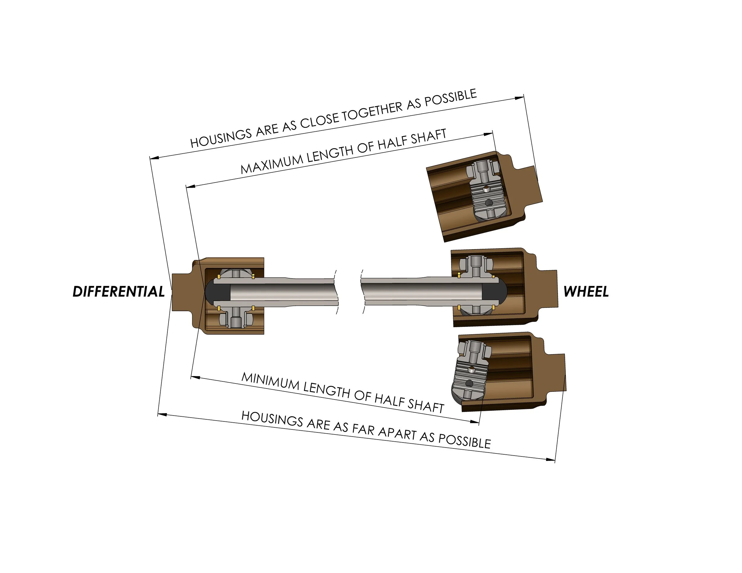
Sweep suspension to find the 3D max and 3D min distances between housings, along with initial estimates of the 3D misalignment angles.
If you cannot find an axle length that meets these requirements you can either change the depth of either housing and/or constrain the travel of the tripod.
When choosing axle lengths for your car, consider any changes that may be made to your suspension or driveline in the future. Changes to ride height, camber, spring preload, differential position and other factors will all affect your halfshafts.
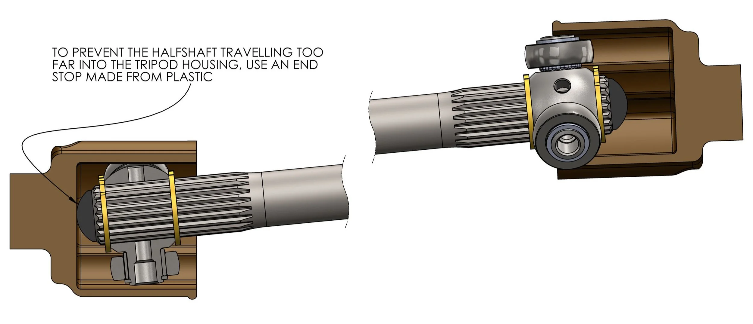
To prevent a halfshaft from traveling too far in either direction a plastic end stop can be inserted into the end of the axle which contacts the tripod housing. These end stops should prevent the tripod lobe from contacting the end of the housing which causes a shock load when the axle bottoms out. This shock load can force the circlip out of its groove or damage the needle bearings inside the tripod lobe.
In their most basic form these end stops are simply pressed into the end of the axle and retained by the press fit. If you’re permanently pressing these into the axle shaft be sure you can remove the tripod bearing and snap rings without having to remove the end stop!
In some cases, one of your tripod housings is much shallower than the other, and the axle shaft needs to be constantly forced into the shallow housing. This can be achieved with a spring-plunger system, where a hole is drilled across the axle which a pin is pressed into, then a spring is inserted which is compressed by the end stop acting on the tripod housing. Verify your halfshaft is strong enough to withstand the stress concentration from the hole before implementing this setup.

If the halfshaft is too long it becomes a suspension component, which in the best case scenario limits suspension travel. More likely, the compressive force on the axle shaft will find the weakest link in your rear suspension or drivetrain and cause it to fail. This often results in breaking the differential mounts, or an A-arm, or a fastener. In rare circumstances the halfshaft can buckle.

Differential mount broken by axial force from a halfshaft that was too long. (Note the bearing forced out of it’s housing.)
A buckled halfshaft

Axle Angle
A common issue is too much misalignment between the differential and wheel hub. The tripod bearings found on many FSAE cars have very limited misalignment. Usually they max at about 12°, but this varies between manufacturers. Beyond 12° the needle bearings inside the tripod will wear rapidly because the angle between the tripod housing and the tripod bearing causes the needle bearings to spin, and the greater the misalignment the faster the needle bearings spin. The only way to resolve this is to move the differential closer in line with the wheel hubs to reduce the misalignment. Misalignment can also lead to interference between the axle shaft and the tripod housings, especially if your tripod housings are very deep.

Tripod Ejection
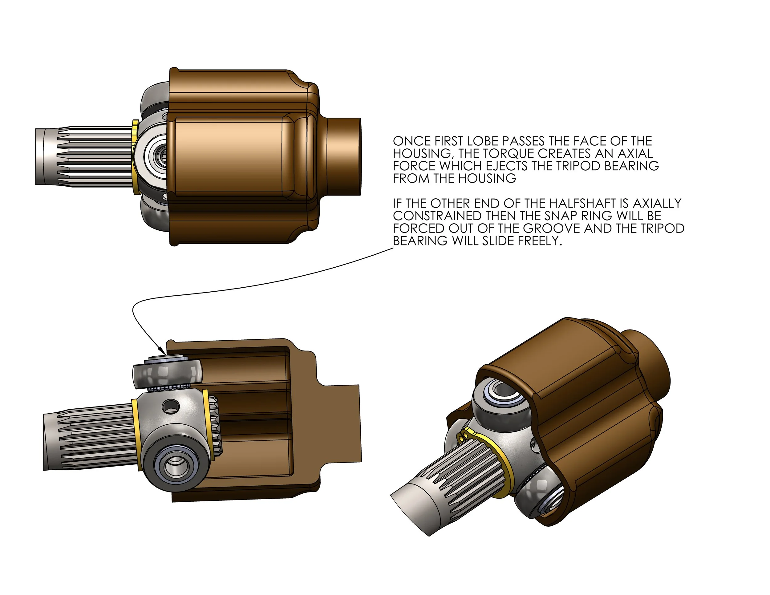
The next common failure is caused by a tripod housing that’s too shallow, OR a halfshaft that’s too short. This allows the tripod bearing to pass the face of the tripod housing, which can be difficult to see because this can happen without the axle shaft falling out. When this happens, the tripod housing applies torque to the tripod lobe at a point off of center, which creates an axial force on the tripod bearing. This axial force through the halfshaft can cause havoc on your drivetrain, either by pushing your differential out of its mounts, forcing the tripod and snap rings to move on the axle, breaking the needle bearing off the tripod bearing, or permanently damaging the tripod housing.
Machining an axle shaft
Many motorsport axle shafts are made from 4340 Chromoly steel, or its modified alloy 300M, which has been heat treated after machining to make it tough, hard, and durable. The inherent drawback to this is that machining the circlip grooves and shortening the axle shaft after hardening can become an incredibly difficult task for an FSAE team. Machining hardened steel requires a harder and tougher tool material, like carbide, but carbide tooling’s worst enemy is an interrupted cut like the axle splines. If you have an option, use the most rigid lathe you have access to.
The most efficient way I’ve seen is to hold the shaft in a lathe and use a tool post mounted grinder (like this) with a thin disc to cut the circlip grooves and cut the axle to length. This allows you to use an indicator to measure the depth of the cut as it’s made, and the grinding disk has no trouble with the hardened steel axle. Use a disc wider than the circlip groove because there is only one critically dimensioned edge of the circlip groove. Be careful to use an actual cut off tool and not a die grinder, as the RPM of a die grinder will often exceed the safe RPM of a cutoff disc and the bearing arrangements are different. Do not adjust the tool axially when making the cut or you can break the disc. Always use appropriate safety equipment.
Boots
The cv boot is a critical part of a working drivetrain. The needle bearings inside the tripod lobes need to be lubricated with an appropriate grease (not just whatever was handy!) and any dirt that finds its way into the grease can cause rapid wear to the bearings and housings. Some teams have come up with creative and lightweight CV boots, like lightweight round latex tubes or cotton t-shirts, and similarly creative ways to retain them to the hubs. CV boots come in all shapes and sizes, so if you need something particular for your application you should consult the EMPI or RCV catalogs.
Leaking grease from a CV boot onto the track is an easy way to earn a black flag during the endurance event, so make sure yours can go the distance without breaking or falling off. When retaining the boot to the hub use a good firm clamp, cable tie, or mechanic’s wire, or design a retaining feature into your hub. On the shaft end, less pressure is often beneficial; if the boot is clamped firmly to the axle shaft then the hot air inside the boot will have no way to escape and can rupture the boot or force it off the hub.
There are some very lightweight alternatives to a rubber CV boot, but their effectiveness varies.


A few notes
Welding axles is an incredibly difficult thing to do well, and requires an extensive understanding of the heat treat process. Avoid welding your axles, or any drivetrain component, if you possibly can.
If you’re making your own tripod housings, ensure that they are hard enough for the contact pressure of the tripod lobes!
It’s good practice to phase the tripod joints on your axle to minimize vibrations and smooth out torque delivery. When you look at the end of your axle the two tripods should be clocked 60° from each other.
A tripod assembly maintains three points of contact, one between each lobe and the housing. Maintain a few mm of end to end misalignment at every point in the suspension travel. Otherwise, if the axle is perfectly aligned with both housings, the tripod assembly can move radially about the housing tolerance, causing vibrations and wear.
