Guide To 2023 FSAE Frame Rule Changes

EV SES process is actually exactly the same.
Keep these resources open during your team’s entire frame design process:
2023 FSAE Rulebook
2023 FSAE Structural Equivalency Spreadsheet (SES)
2022 FSAE Tech Inspection sheet
2023 suspension subteam geometry and loads
2023 ergo subteam packaging
2023 drivetrain subteam packaging
The Guide To 2022 Frame Rule Changes has details about even more rules.
There are other rule changes not mentioned here. Just frame and SES topics are covered. And I have skipped over everything that is simply a clarification of existing 2022 policies.
2023 North American SES submission should open one day after 2023 North American registration.
In a perfect world:
Teams submit EQ SES early in the season
Zero teams leave things to the last minute
Well engineered designs obviously follow all rules
Review and approval are quick and easy
Teams are approved as early in the season as possible
All teams are approved before competition
Teams build approved frames
Leave build tolerances where there is a rules measurement
Do not design right on the limit.
Most tube paths without a rules measurement can move a few mm, we will never know the difference
Cars quickly and easily pass frame inspection
Frame matches SES
Measurements pass easily
Zero teams make chassis modifications at competition

Stay inside the system and expectations for safety critical systems. Don’t risk a situation where an inspector can look at a car, and refuse to sign off. In addition, the goal of Tech Inspection order is to inspect as many teams as possible on the first day.
The lag time for teams to make fixes for SES approval influences mechanical inspection number.
A measure of completeness, not submission date
Submission date is the tiebreaker
Minus waiting on the reviewer
normalized for difficulty between IC/EV, Tube/Mono
The quality and completeness of the ESF and accumulator video influence electrical inspection number.

Half the teams got everything sorted out in less than a month in 2022. They went to the front of the Tech line.
Rule Changes Affecting All Teams
F.8.2.4 Front Chassis Protection
25mm gap required between AIP + Front Bulkhead + Diagonal and the pedal assembly.
Historical test data shows diagonal and AIP deflection in an impact, so there needs to be a space between those and the driver’s feet.
F.5.14 Steering Rack Protection
It is strongly preferred to locate the steering rack inside the chassis.
If the steering rack is above or below the chassis, it needs a tube in front of it. Or equivalent.
This protects the steering rack from being pushed backward by a curb or guardrail.
Monocoque teams attaching tube protection must show attachment equivalence.
I expect adding monocoque FBHS height in front of the rack is the easiest approach.
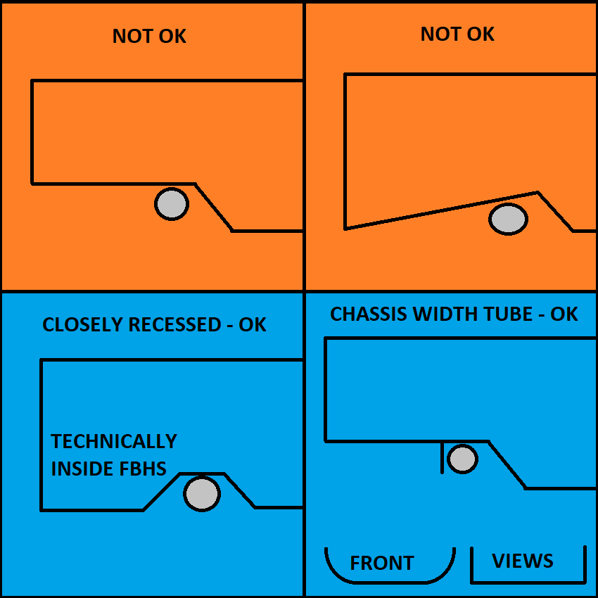
The same concepts apply to steering racks located above the chassis.
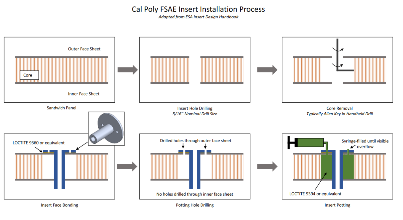
F.8.5.2.a known Good Adhesives For Honeycomb Attenuators
To make the SES process easier for new teams and reviewers, we have identified a number of good choices for bonding standard honeycomb attenuators. Other adhesives can be approved if peel values are provided for Aluminum and the AIP material. We expect a receipt or other proof of the adhesive used. Good practice suggests safety critical adhesives should be a yearly purchase.

Rule Changes Affecting IC Teams
T.6.1.3 Cylinder Material
Compressed gas cylinders/tanks spaced less than 150 mm from the exhaust must be metal, unless all three types of heat transfer are addressed per T.1.6.3. The concern is a composite matrix losing strength at high temperature.
T.5.5.4 Drain Holes
2x 25mm drain holes are required at the lowest point of the chassis to prevent fluid accumulation.
2x 25mm drain holes are also required between the fuel tank and driver.
If the lowest point of the chassis is between the driver and the fuel tank, a total of two holes will satisfy both requirements.

Rule Changes Affecting EV Teams
F.10.5.2 Accumulator Container Mounting
Accumulator mounts must not be located on the Shoulder Harness Bar, the Main Hoop above triangulated side structure, or on the Main Hoop Brace.
Tall accumulators are also more likely to fail the tilt test.
Don’t mount anything in the middle of those tubes: No wing mounts, no engine mounts, no suspension mounts.
Keep those mounts on nodes or other tubes.
F.11.2.1.c, F.11.2.2.b HV Side Protection Height
The Rear Impact Structure must be at least 240mm above the lowest point on the chassis (see F.6.4.4.b).
For 2023, there is no height maximum for the top of the Rear Impact structure.
The Upper HV Protection path runs from the Upper Rear Impact Structure to the Upper Side Impact Structure.
For shorter accumulators, the Upper HV Protection may be lower in the middle.
Monocoque EV teams will have to account for openings in the rear impact structure in SES math. If monocoque equivalence is used for the rear impact structure, especially at the very back of the car, no openings is strongly preferred.

Rule Changes Affecting Tube Frame Teams
F.5.3.3 Cap transverse tubes
Chassis tubing must have any open ends closed by a welded cap or inserted metal plug. This is targeted at transverse tubes interrupting a regulated path, such as FBHS, SIS, or MHBS.
The bottoms of the Front Hoop and Main Hoop may be left open. The rules treat these as bulkheads, and the holes are good for drainage.
Make sure to follow good welding practice, including vent holes.

F.5.6.2 Roll Hoop bends
Below the Upper Side Impact, any front or side view bend in the Front Hoop or Main Hoop must be triangulated in side view on at least one side.

Rule Changes Affecting Monocoque Teams
F.4.3.1.a engrave test panels
Engraved means “carved or scratched into surface” of test samples.
Include build date, test date, sample name, and peak test force.
Following material ordered for testing, we will grudgingly accept builds from minimally spaced orders of the same specification material from the same supplier.
All new builds:
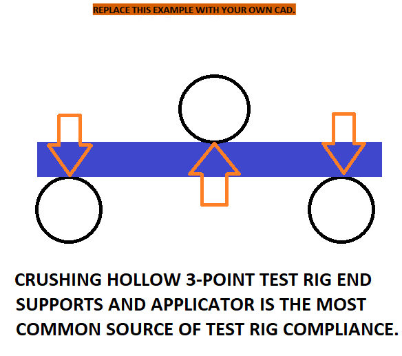
There is no SES rig compliance correction.
This led to too many unrealistic results.
Work to eliminate rig compliance (usually due to using hollow applicator or span support tubes).
Select the maximum sustained linear portion of the tube and panel tests to maximize derived results.
We will work with teams who have older builds that are competing for the first time.
F.8.4.3 Mono FB Diagonals May Attach To AIP

Large front bulkheads or standard honeycombs require diagonal equivalence (with the material located on the actual diagonal), or testing to show <25mm deflection. We really want you to take a diagonal option. Tube teams simply weld in a diagonal. The three best monocoque approaches with no test required are:
Front bulkhead with no opening, equivalent to the three tubes replaced
Weld a square steel or aluminum tube to the AIP diagonally across the opening.
Bond a square tube to the AIP diagonally across the opening.
It is possible to:
Use removable panel covering the whole bulkhead.
Laminate a diagonal shape with holes on either side into a Front Bulkhead.
Attach a tube or equivalent in other ways to the AIP or FB.
F.8.2.2 AIP Attachment
Welded AIPs must reach the centerline of the FB tubes.
All other AIPs must extend to the full perimeter Front Bulkhead.
If bolted: 8 bolts are required.
It is recommended to put the thread side forward for visible inspection.
Trimmed to just over 2 threads past the nut and washer.
If bonded (monocoque): The Front Bulkhead must have no openings.
If Laminated (monocoque with FB opening): The AIP must be in front of the outer skin of the Front Bulkhead.
The AIP must be fully enclosed, and have shear capability >=120kN.
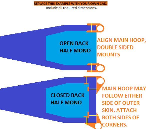
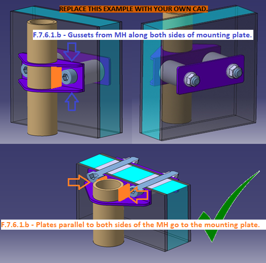
F.7.8.2 Half Mono MHBS attachment
If a tube frame subject to F.6 or F.11.2 attaches to the monocoque, one of two mount designs is required:
a. Parallel brackets attached to the two sides of the Main Hoop and the two sides of the monocoque.
b. Two mostly perpendicular brackets attached to the Main Hoop and the side and back of the monocoque
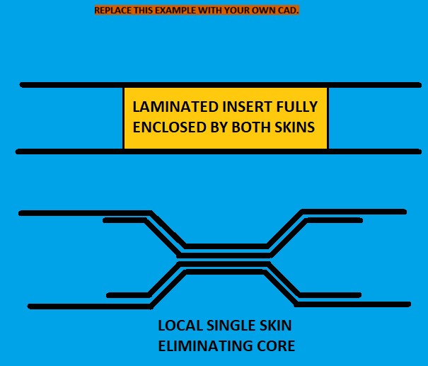
F.7.8.8 attachment points
Each attachment point must contain one of the two:
a. A solid insert that is fully enclosed by both the inner and outer skin
b. Local elimination of any gap between inner and outer skin, with or without repeating skin layups
This will be enforced for roll hoop, main hoop brace, and accumulator attachments.
Courtesy of your colleagues at Cal Poly SLO Racing:
It is possible to create a post-cure insert between two intact skins.
An allen key is a little questionable compared to a proper removal tool.
F.7.9.2 Sh Testing Angle
Lap and anti-submarine belt attachments must be tested normal to the monocoque panel.
Shoulder belt attachments
Should be tested 90 degrees to the monocoque panel.
May be tested at any angle above the higher of:
Installed belt angle
45 degrees absolute minimum
Engrave samples per F.4.3.1.

F.7.6.1 Box Roll Hoop Gussets
Add plates parallel to the Roll Hoops to fully box the tube mounting plate.
F.4.3.7 Lap Joint Test

Adhesive test requirements are most frequently triggered by:
Bending loads, such as bonded accumulator mounts.
Carbon-carbon cold bonds, such as a post-cure Front Hoop enclosure.
Or post-cure accumulator container walls and floors.
For 2023, it will be good engineering practice to run these tests for bonding chassis halves longitudinally.
But they will not be part of the SES process.
Bonds through a composite MHBS region may be scrutinized.
Vertical cold-bonds between chassis sections will absolutely require testing.
F.7.4.3 Fully Laminated Front Hoop
Fully laminating means encapsulating the Front Hoop around its whole circumference

F.3.5.3 Aluminum Tubing
2mm wall is permitted for unwelded aluminum Front Hoops that are fully laminated into the monocoque. For 2023, any brackets or bolted connections will trigger the increase back to 3mm.
If your team is interested in developing a process to possibly allow welded or brazed aluminum in thinner walls in future rules, please get in touch.
F.7.1.3 Core In Monocoque Corners
Corners between panels used for structural equivalence must contain core. This includes the SIS vertical to SIS floor connection, and any section where the Izz option is selected for equivalence.

F.5.1.2 Hybrid Attachment
Composite panels replacing required diagonals between upper and lower tubes must be bolted and meet F.7.9 at all four corners (assuming rectangular shape.)
Composite diagonals may be fully laminated around regulated perimeter tubes. Equivalence to the mounts replaced must be shown in the SES.
