Changing Gear Mechanically
Your data shows that it’s taking forever to shift. Drivers complain that it’s rough, it’s inconsistent, that they’re ralphing the gears all over the place and filling the crankcase with hardened steel shards. Worst of all, they’re driving whole sections of the track in the wrong gear just to avoid having to interact with the contraption that’ll let them select another ratio. A new system may be called for using an electric motor, or a solenoid, or some hydraulics, or some pneumatics, but why not take this chance to learn something about mechanical systems?
Travel, Backlash, Deflection
Figure 1: Travel

Travel - The movement a mechanism must move to perform its function. In this case, this can be considered either the distance the end of the J-arm must move, or the angle the shift shaft must rotate through, to select the next gear
Figure 2: Backlash

Backlash - Lost motion between two parts of a mechanism due to clearance within an assembly, either necessary to allow the operation of a bearing, or to prevent excessive interference and friction when it is heated, or unnecessarily introduced by an inability of a joint to take up manufacturing inaccuracy. It can be measured by locking the working end of the linkage and measuring the distance that a minimal force can move it - often specified as the clearance that a feeler gauge can go into smoothly.
Figure 3: Deflection

Deflection - Lost motion due to the limited stiffness of any machine component - the difference between the distance one end of a rigid body must move to perform a task at the other end and the distance the driving end of the actual part must move to do so.
In order to change gear, the driver must move the gear lever far enough to:
Take up the backlash in all of the bearings
Deflect the linkage far enough to provide enough force on the J-arm to move it
Move the J-arm through its full travel to engage the new gear.
A return spring is part of the engine’s shift mechanism to allow repeated up- and down-changes, so you will need to ensure that there is low enough friction in the shifting mechanism for that spring to re-center.
Bearing Stiffness, Contact Area, Degrees of Freedom
Figure 4: Spherical Bearing and Oilite Bushing

A bearing allows movement in some directions while transmitting force in others. A spherical joint, such as a ball joint or rod end, allows rotation about two axes. A revolute joint, such as an Oilite bushing or a ball or needle bearing, allows rotation about one axis. All other degrees of freedom are constrained; without relative movement a force must be transmitted.
A two-degree-of-freedom joint makes initial contact at one point; it must be able to maintain free movement about both axes. A one-degree-of-freedom joint makes initial contact along one line, as movement about the other axis of rotation is constrained by its geometry. Hertzian contact stresses can be calculated for both scenarios with various inputs of clearances and elastic moduli of parts and liners. This usually shows the revolute joints as radially stronger and stiffer than the spherical ones at the same diameter. If you find a stiffer revolute bearing solution than a Super Oilite bronze flange bushing with a 0.3% diameter clearance running between a steel shaft and a steel housing, please write to me.
The linkage must have an adequate number of degrees of freedom, with each component constrained to move the next part in the linkage. If every joint is a revolute joint with no lateral backlash, then any linear misalignment from end to end will cause binding - a preload on both joints caused by the need to deflect them to reach a geometric state where they can move. One pitfall to avoid is a linkage that is free when the engine, seat, and gear lever are in their nominal positions, but binds when the engine moves laterally, longitudinally, vertically, or rotates due to the forces generated when accelerating the car. Each link starts with six degrees of freedom - they do not have to end with only one if the other is trivial. A tube with spherical joints on each end can move on the path defined for those joints by their links, or rotate around the central axis of the tube, but that second rotation only causes problems if the spherical joints strike another component.
Link Stiffness, Ultimate Strength, Fatigue Strength, Weight
Figures 5-8 generated by MSC Apex with the same loads and constraints.
1000N load applied with 5 mm eccentricity on a 20 mm OD 1 mm wall thickness steel tube.
These figures appear courtesy of Aptera Motors Corporation, San Diego CA.
Figure 5: Straight Link: Maximum Deformation 17 Microns
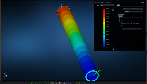
Figure 6: Link Bent 1 Diameter in 20: Maximum Deformation 569 Microns (1/33 stiffness of straight link)

Figure 7: Straight Link Maximum Stress 19.6 MPa

Figure 8: Bent Link Maximum Stress 93.2 MPa, 5x Stress of Straight Link

It’s clear from these four figures that straight links are more efficient than bent ones. Other design judges would use these to harp on for twenty years. A local kart manufacturer saw them and immediately gave all of his bent seat struts away to his competitors. A more important conclusion is to pay attention to magnitudes as much as differences - the less efficient link deflects ½ mm. How much mechanical advantage does your shift lever have to have for you to put 1 kN into the shift rod? What effect does that have on the driver’s shift throw? Do you gain an advantage from a J-arm so short that it takes 1 kN to move (it’s possible to find one!)
Efficient means of transferring force are different over different intensities of force and length. A pair of cables running the length of an MD-80’s fuselage from the control column to the elevators only have to operate in tension, and a rigid link that long would need a large cross section to avoid buckling. Douglas engineers chose cables because such a rod would be a very effective battering ram for the Douglas fabricators and assemblers to get into the Douglas engineering office with.
This is a good example for another reason: on a 75-ton, 150-passenger jet, efficient mechanical and aerodynamic design allowed the flight controls to be entirely manual. Good engineering made the control forces and work low enough for the pilot. You can guess what I think about power steering on a passenger car and you won’t need two guesses.
In the case of a FSAE shift linkage, consider the cross sectional area and elastic modulus of the actuating mechanism. You can’t push a rope, but if you let steel wire stack up against the sides of a housing as it buckles, a push-pull cable can be made to work, with stiffness that defies analysis and friction that defies tribology.
| Mechanism | Cross-Sectional Area | Equivalent Area In Steel |
|---|---|---|
| Steel Tube, 20mm OD, 1mm Wall | 63 mm^2 | 63 mm^2 |
| Al. Tube, 20mm OD, 1mm Wall | 63 mm^2 | 21 mm^2 |
| Steel Rod, 9mm OD | 63 mm^2 | 63 mm^2 Make sure to calculate buckling load before substituting! |
| Steel Cable, 3mm diameter | 7 mm^2 | 6 mm^2 Stress concentration in individual fibers as they cross. |
| Zylon Cable, 3mm diameter | 7 mm^2 | 9 mm^2 With the mass of a steel cable with area of 1.2 mm^2. |
| Brake Fluid, 5mm rigid line | 20 mm^2 | 0.4 mm^2 Assuming that the rigid line is itself inextensible. |
Actuation Force, Friction Force, Work, and Driver Feedback
The shift shaft takes a predictable moment to turn over a fixed angle needed to move the shift force a fixed distance to change gears. With a J-arm attached to the shift lever this can be measured as a force and distance. The stock J-arm from a Big Four motorcycle is abuse-tolerant - your hand on any gearlever that will fit in a car is not the foot of a motocross rider who’s missed the peg on a jump and is now going to downshift as soon as the wheels touch down. This doesn’t apply once you’ve heated it, bent it, chopped it, or drilled through it.
Using a spring scale you can measure the actuating force, using a machinist’s rule you can measure the travel. If you take several measurements of force over the travel you can integrate and find the work needed. If you multiply the maximum force by the travel you have an appropriately pessimistic estimate of the work. Work can be supplied either directly by the driver or by the use of the kinetic energy of a heavy gear knob - shifter karts often have 200g of solid steel here.
Backlash adds travel, and the force needed to take up the backlash is a direct way to measure your friction. A lot of friction will be added if the linkage rubs against anything on its way from the gearlever to the J-arm - unfortunately, there is no grease that will allow it to slide against the seat easily. Any force signal smaller than the static friction force will not reach the driver. At best, this slows the gearchange down, as they are not certain that they are in the next gear yet, and have to push the lever to the end of its travel. At worst, the driver has to positively move the lever back to its starting position.
Conclusion
A good mechanical gearchange allows upshifts in 50-75 ms, measured between the end of positive vehicle acceleration in the lower gear and the start of positive vehicle acceleration in the higher gear. If you have an adequately stiff and tight mechanism with low enough friction, the driver won’t give you much feedback about it - they only notice if it’s bad.