Coarse-To-Fine Design
“Some tools are chainsaws. Some tools are scalpels. Know when to use each.”

Employ Systems Engineering Principles
Design from the Top-Down: Vehicle, Subsystem, Part
Validate from the Bottom-Up: Part, Subsystem, Vehicle
Simulate What You Test - Test What You Simulate
Improved Simulation Tools
Improved Test Procedures
Correlation between Test & Simulation
Quick, and Easy Interchange of Data Between Simulation, Test, and Design Activities is a Critical Success Factor.
SYSTEMATICALLY REDUCE THE SOLUTION DOMAIN
Utilize the data that exists in each stage of the design
Utilize Systems Engineering Rolldown Processes
Simple tools using little data are used to reduce the solution domain from a near infinite size to a finite, manageable size very early in the vehicle program.
Discipline is required to only work within that reduced domain.
Increasingly sophisticated tools and correspondingly more data is then required to further reduce the solution domain to a single solution.

AS YOU MOVE DOWN THE HIERARCHY,
YOU TRADE INSIGHT FOR ACCURACY
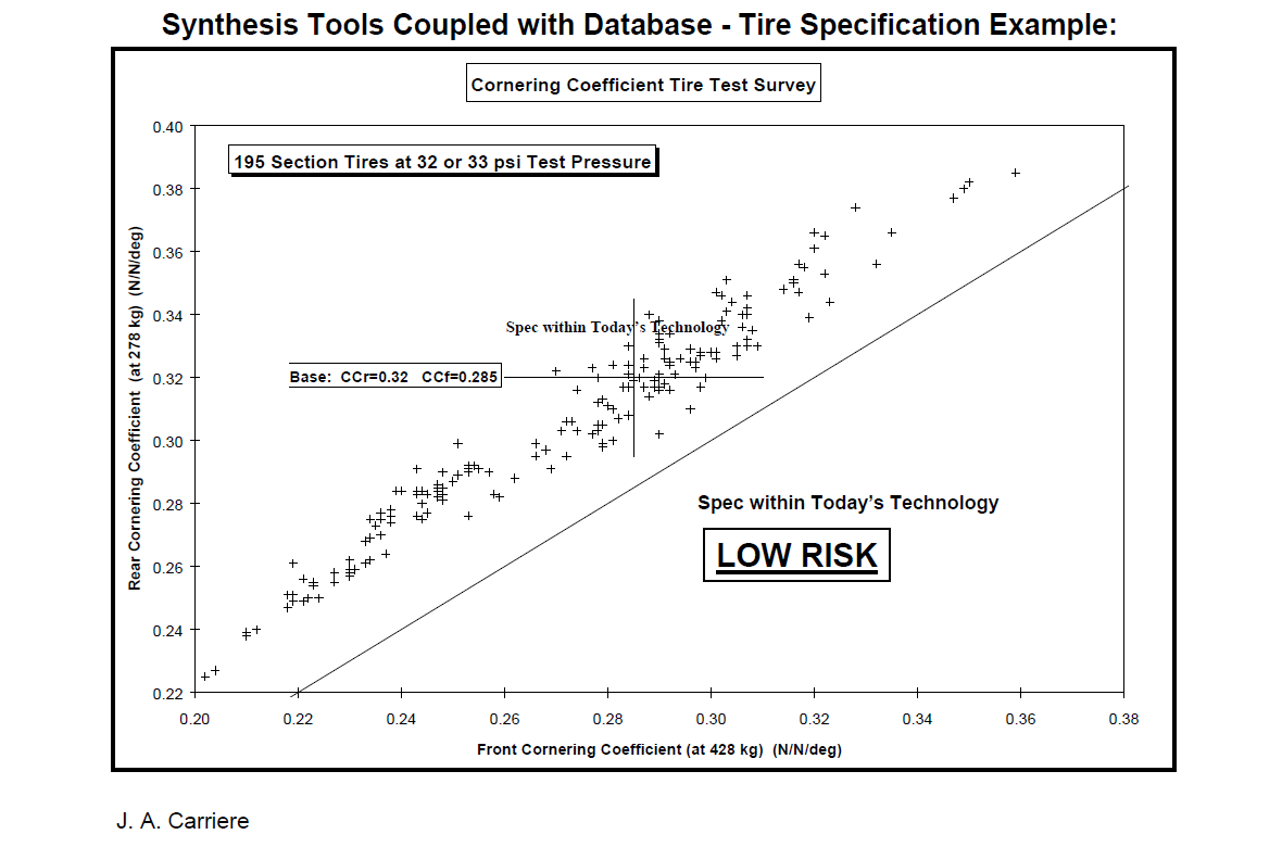
(1) Empirical / Statistical
Predictive regressions based on results in databases.
e.g. mass vs. plan view area, fuel economy vs. performance, tire cornering performance vs. rolling resistance
Effective for conducting high-level tradeoffs very early in the design.
These simple, powerful tools should be used extensively in the Advanced Design phase.
There are many of these tools yet to be developed, as the databases needed for creating these relationships are either not available or not accessible.
Once these databases are available, data mining activities will unearth additional useful statistical relationships.

Predicting total vehicle mass with reasonable confidence base on only the statistical influence of basic measurements.
Check performance requirements against existing examples.

Requirements that are at or beyond the extremes of existing examples might be unworkable.
(2) Parametric (Synthetic)
These models use a small number of parameters to “capture the essence” of the performance or design characteristics of the system being modeled.
A parametric linear handling model with 5 parameters can be used to describe the basic linear handling of a vehicle with reasonable accuracy.
These tools can be used to synthesize vehicle, sub-system, or component performance specifications early in the design.
Parametric models provide significant INSIGHT to what parameters affect performance.
Design issues because of performance sensitivity or design sensitivity to these parameters can be easily determined.
(3) Parametric (Analytic)
These models use a larger number of parameters to represent the performance or design characteristics of the system being modeled.
These parametric models with more than 100 parameters can be used to describe performance with greater accuracy.
These tools can be used to analyze vehicle, sub-system, or component performance specifications once values for the input parameters have been identified.
Most will be retrieved from databases
As the models become more complex, less INSIGHT to performance or design issues is afforded due to the larger number of parameters involved and their
interactions.
(4) Discrete, Multi-Body, Finite Element
These models require vast amounts of data to describe the physical characteristics of every element in the system being modeled.
These models can potentially describe performance with the greatest accuracy as all the characteristics of the vehicle, sub-system, or component
are embodied in the representation of the elements/parts.These models are used for verification/validation, and provide little INSIGHT to performance or design issues due to the even larger number of parameters and their interactions.
(5) CAD
These models provide a detailed 3-D geometric representation of the vehicle, sub-system, sub-assembly, or components.
This includes all surfaces, features, assembly, and kinematic relationships.
These models require very large data structures to provide this type of detailed description.
These models are used for detailed visualization and documentation of the components.
Styling, packaging and interference checking are the main uses of the tools.
The data can be used to generate numerically controlled machining information.
These models can also predict CG characteristics if the density properties are included.
(6) MANUFACTURING/CAD
These models provide a detailed 3-D geometric representation of the tooling used to build components as well as the manufacturing tooling.
This includes all surfaces, features, assembly, and kinematic relationships.
These models require even larger data structures to provide this type of detailed description.
These models are used for detailed visualization and documentation of the tooling and assembly hardware.
Packaging and interference checking are the main uses of the tools.